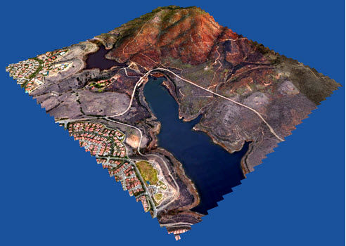
| Import curvature corrected high resolution tiled images |  All license types, no extra cost. All license types, no extra cost. | Only in Business or Enterprise versions at an additional cost. |
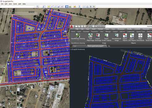
| Import objects from Google Earth™ or from KML/KMZ files. | Dialog box provided to set importing options. | No graphical interface. No importing options provided. |
Export drawing entities to Google Earth™ KML/KMZ files
| Dialog box provided to set exporting options. | No graphical interface. Point and text objects can’t be exported. |
Export a drawing as an image overlay to Google Earth™
| Options to set background color and transparency. |  Feature not provided. Feature not provided. |
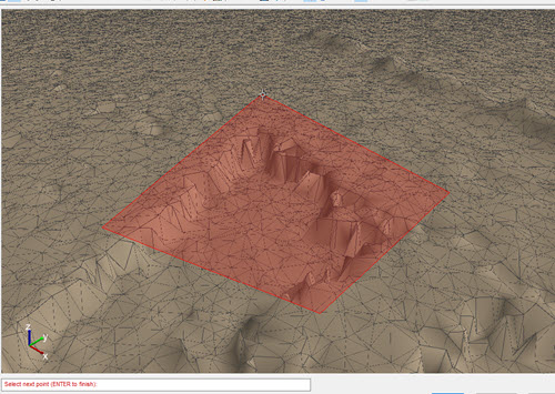
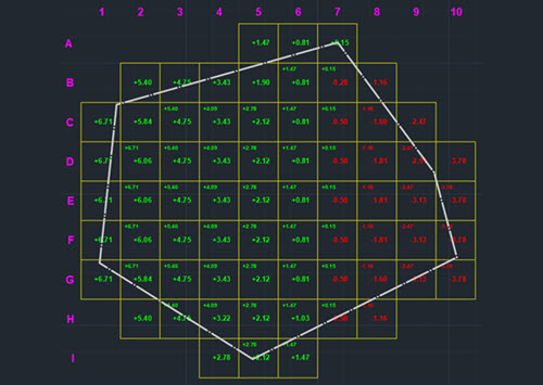
Import terrain mesh inside a closed polyline.
| Dialog box to set grid resolution and rotation, mesh properties and show the grid in Google Earth. | No graphical interface. Mesh resolution, grid spacing, resolution and rotation can't be set. |
Import terrain mesh along a path.
| Distance to the left and right and between stations can be set. | Feature not provided. |
Commands to edit terrain meshes.
| Invert, delete and cut triangles, refine mesh border, insert, delete, flatten and move vertices among others. | Feature not provided. |
Export 3D models to Google Earth™
| Dialog box to set view heading and tilt. | No graphical interface. View options can’t be set. |
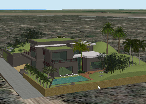
Import 3D models from file
| Import from DAE, 3DS, FBX, OBJ files. Options to select linear units, Z-Up direction, merge coplanar faces and shade the model. | Feature not provided. |
Import terrain mesh from text file
| Dialog box to select the file format, data and decimal separator. File can be previewed before importing. | No graphical interface. X, Y, Z column numbers and data delimiter must be manually specified. File can’t be previewed. |
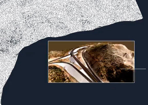
Import terrain mesh from LiDAR and DEM files.
| Mesh properties, refinement options and other processing parameters can be specified. An area to process can be selected. | Feature not provided. |
Import terrain mesh from LandXML file.
| Dialog box to preview mesh information and set mesh properties. LandXML files from Civil 3D™ can be imported. | Feature not provided. |
Create terrain mesh from points.
| Mesh properties such as name, description, color, layer, visualization mode, linear units, and boundary parameters can be specified. | No graphical interface. Mesh properties can’t be set. Mesh boundary can’t be refined. |
Create mesh from polylines
| Dialog box to set mesh properties. 3D polylines can be selected. | No graphical interface. Mesh properties can’t be set. 3D polylines can’t be selected. |
Create mesh from 3D faces.
| Dialog box to set mesh properties. | Feature not provided. |
Export terrain mesh to LandXML file
| File created can be imported by Civil 3D™ and other CAD software. | Feature not provided. |
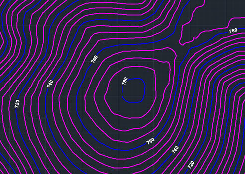
Terrain mesh visualization styles.
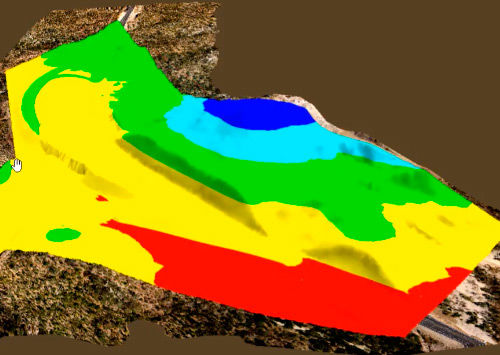
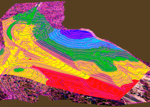
| Predefined elevation and slope ranges styles can be selected, created and saved. Mesh can be visualized as contour lines, points, boundary, slope arrows or a combination of several styles. | Only elevation, slope and direction ranges can be visualized. |
Historical imagery.
| Historical imagery date can be selected in Google Earth before importing the image.* | Historical imagery can be selected at an additional cost. |
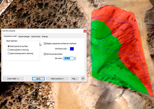
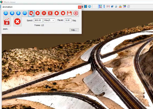
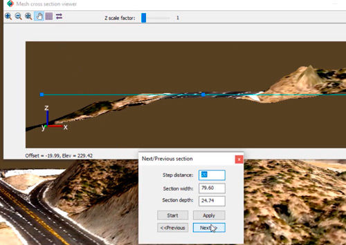
| Mesh 3D Viewer | Instantly get cut-fill volume calculations, view the surface by elevation or slope ranges, display instant contour lines, create videos, measure distance, slope and angles directly on the mesh, and inspect cross sections. | Feature not provided. |
| Mesh Explorer | Tool to organize your projects and access mesh importing, editing and visualization commands from context menus. | Feature not provided. |
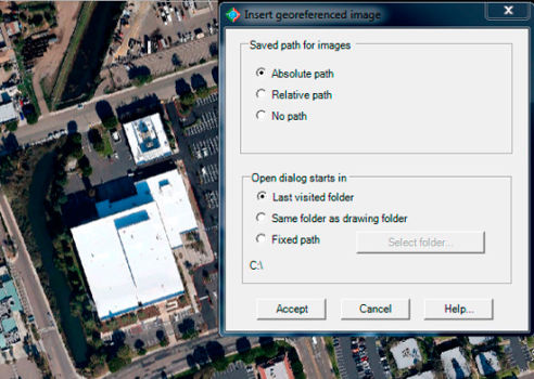
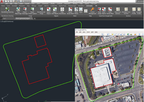
| Insert georeferenced image | Dialog box to select image path type and initial directory. Option to save image within drawing. | No graphical interface. No option to save image within the drawing. |
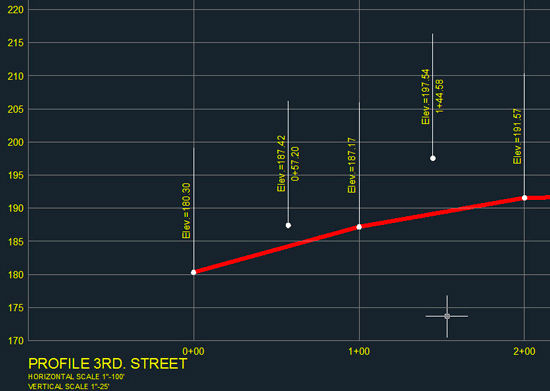
| Get cross sections and profiles from terrain mesh | Options to set elevation, station and scale annotations. The user can specify the color, layer, text style, size and placement for each profile and cross section element. | Feature not provided. |
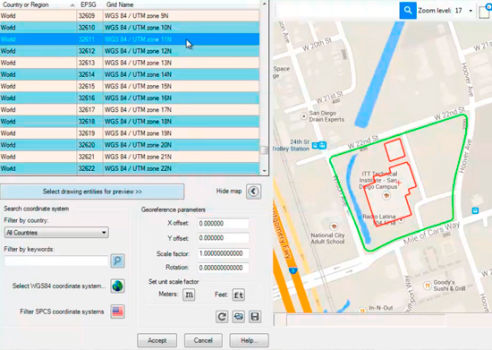
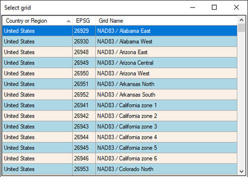
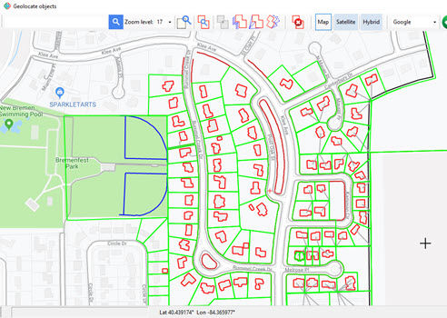
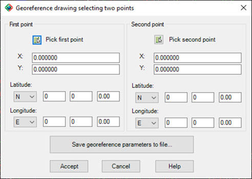
| Georeferencing. | The drawing can be georeferenced by selecting a coordinate system, locating drawing entities on a map, selecting two points in the drawing , or by loading georeference parameters from a file. AutoCAD™ and Civil 3D™ georeference parameters are recognized. | The drawing can be georeferenced by selecting a coordinate system, selecting a point or typing lat/long coordinates. Georeference parameters defined by AutoCAD™ or Civil 3D™ are not recognized. Latitude / longitude values can’t be entered as degrees-minutes-seconds. Grid rotation can’t be specified. |
| Insert images, objects and terrain meshes without georeferencing the drawing. | You can specify any point in the drawing and the insertion units, if you don’t need them to be georeferenced. | Feature not provided. |
| Technical Support | You can submit a support ticket, contact us by chat at our webpage, by email or get remote assistance by TeamViewer at no extra cost. | Support is offered only by email or by submitting a support request at their website. |