Features
Import images to CAD
from different providers in satellite, map or hybrid mode at different resolutions.
Export AutoCAD drawings to Google Earth™
Export CAD drawings to Google Earth as image overlays in full color, grayscale or B&W, in different image formats (BMP, JPEG, TIFF, PNG, GIF). Background color and opacity can be adjusted. Multiple screenshots can be taken to increase the final image resolution.
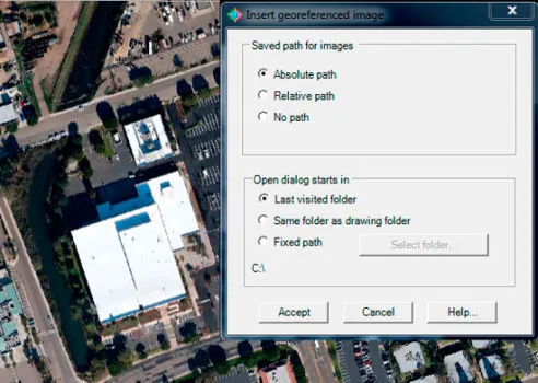
Insert georeferenced images
Accurately place an image world file with spatial data in your drawing, applying XY scale and translation transformations. Use this command to insert images having the corresponding world file with spatial data information. CAD-Earth has the option to create world files when importing images from Google Earth.
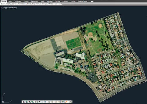
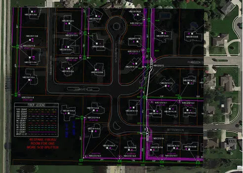
Import Google Earth image to CAD
Images can be imported from major service providers (Google, Google Earth, Bing,) in different resolutions (Normal, medium, high, highest) and image modes (satellite, map, hybrid) in full color or grayscale in major image formats (BMP, JPEG, TIFF).
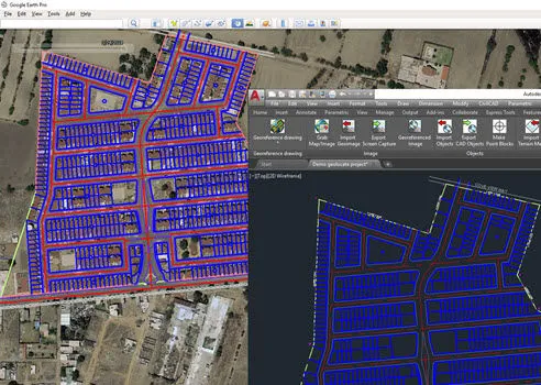
Easily import & export objects
between CAD and Google EarthTM
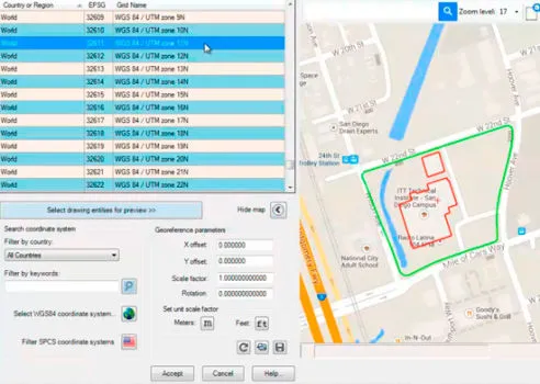
Preview position of entities in a map
You can preview the position of selected drawing entities in a map when selecting a coordinate system to georeference a drawing. Drawing entities can be moved, scaled or rotated in the map until they match the site.
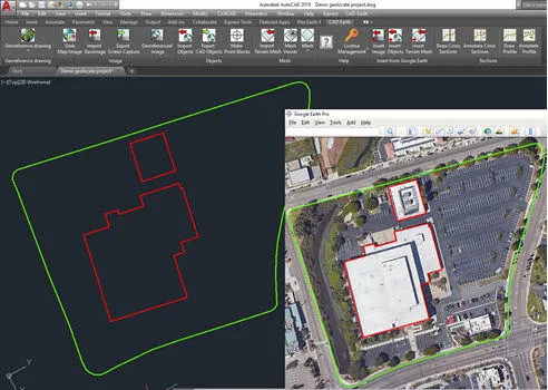
Import Google Earth™ objects to AutoCAD
Images can be imported from major service providers (Google, Bing, Yahoo, Ovi) in different resolutions (Normal, medium, high, highest) and image modes (satellite, map, hybrid) in full color or grayscale in major image formats (BMP, JPEG, TIFF).
Export AutoCAD objects to Google Earth™
Export CAD drawings to Google Earth as image overlays in full color, grayscale or B&W, in different image formats (BMP, JPEG, TIFF, PNG, GIF). Background color and opacity can be adjusted. Multiple screenshots can be taken to increase the final image resolution.
Get contour lines,
profiles and sections from Google EarthTM
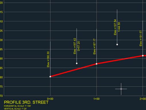
Profile and sections from mesh
After a terrain mesh is imported to AutoCAD®, a polyline can be drawn to indicate a path where a profile and sections will be extracted. Station lines with chainage annotations will be inserted along the polyline, and the corresponding profile and sections will be created, complete with elevation, station and scale annotations. The user can specify the color, layer, text style, size and placement for each profile and section element.
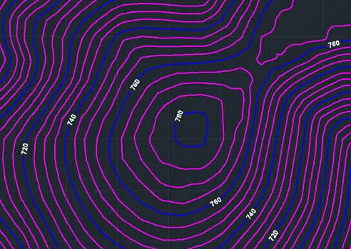
Draw contour lines in AutoCAD®
Selecting an existing terrain mesh contour polylines can be created. Vertical separation, layer, color and smoothness factor for contour polylines and the text layer, color, size, prefix, suffix, decimal places and placement options for contour labels can be specified. Existing contour polylines will be automatically updated if settings are changed.
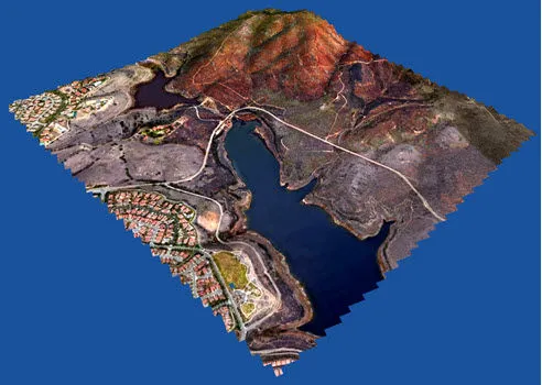
Import Google Earth™ terrain
A terrain mesh can be imported selecting an existing closed polyline or along a polyline path calculating point elevations. By specifying the origin point, rotation angle and and mesh resolution the density and precision can be adjusted. The resulting mesh can be processed to get contour lines, dynamic profile and section drawings complete with annotations. You can link the site image to the mesh when importing.
Easily georeference
your drawing.
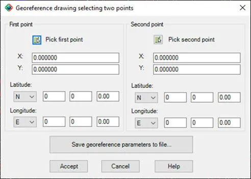
Georeference your drawing selecting two points
If you know the corresponding latitude and longitude coordinates of at least two points in your drawing the georeference parameters can be calculated with this information.
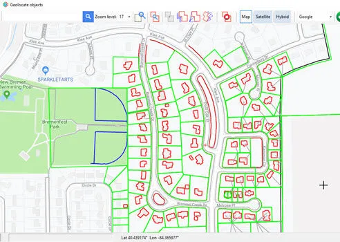
Georeference your drawing placing entities on a map
Georeference your drawing selecting some reference entities in your drawing (like lines, polylines, arcs and circles) and locating them in a map. You can move, rotate and scale the reference objects until they are correctly placed.
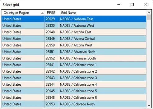
More than 3000 coordinate systems available
Convert accurately between any coordinate system in the world and Google EarthTM. If you have georeferenced your drawing using AutoCAD® commands, CAD-Earth® can use this information to convert coordinates when importing or exporting objects, images and terrain meshes.
New in CAD-Earth Premium!
Instantly get cut-fill volume calculations, display the mesh by elevation or slope colors, show contour lines, create animation videos, and much more.
Terrain Mesh Viewer
(CAD-Earth Premium)
Display instant contour lines
Contour lines can be displayed defining line color, the gap between them, and the base elevation. When you change the camera position or direction, the contour lines are instantly updated.
Creación de videos de animación
Se pueden crear impresionantes animaciones de video que definen la posición de la cámara y la dirección de la vista, la velocidad y el tiempo de pausa. El archivo resultante se puede abrir en cualquier reproductor compatible con mp4, como el Reproductor de Windows Media. También puede guardar y cargar secuencias de animación.
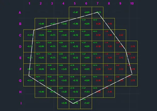
Earthwork volume calculation and reporting commands
Perform cut/fill volume calculations by the grid method. Every element of the grid can be customized, specifying line type, color, layer and scale, text size, style, and color. Get an earthwork summary report in Excel® format.
Inspect an ortographic view of a mesh cross section
Commands to insert, delete, move, and flatten mesh vertices and triangulation. Import mesh from LiDAR, and GeoTIFF, and text files. Create, edit or select predefined mesh visualization styles.
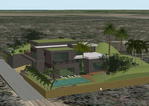
Export 3D models to Google Earth® or import them from a file.
3D models can be imported from files in different formats (DAE, 3DS, FBX, OBJ). Once the 3D model is inserted in the current drawing as a block, it can be rendered, shaded, copied, rotated, scaled, moved, and measured as a regular entity.
Insert a screenshot of the current view
Selecting various predefined resolutions, and save it to an image file or insert it in the current drawing as a raster image reference.
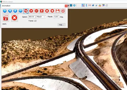
Create animation videos
Awesome video animations can be created defining camera position and view direction, speed and pause time. The resulting file can be opened in any mp4 compatible player, such as the Windows Media Player. You can also save and load animation sequences.
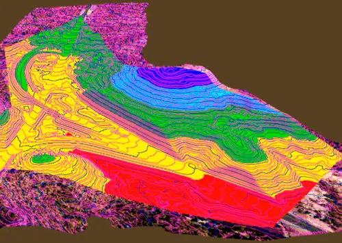
View the surface by elevation or slope ranges
The mesh can also be displayed with colors according to defined elevation and slope ranges. The color can be applied to the whole surface, defining points on the surface, or selecting a closed polyline in the drawing. The total calculations will be shown instantly for each range.
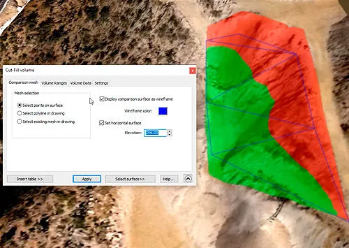
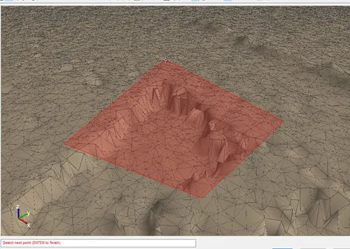
Instantly get cut-fill volume calculations
Get instant cut-fill volume calculations by selecting polygon points on the surface, an existing polyline or a mesh in the drawing. The area will be colored according to the depth and color defined for each cut-fill range. You can insert a summary table, along with the plan view in your drawing.
See comparisons of the
advantages of CAD-Earth over the competition.
Start your free trial now!